Manus Et Machina
Engineering Design Studio (A5, 015)
Saturday, September 16, 2017, 11:50 am – 13:05 pm
Prelude
- Attendance list
- About Physical Computing
- Auto-activity, Re-activity and Inter-activity
Introduction to Arduino
There are many many different types of software languages, the ones that I think are most interesting are the least useful to us. Generally speaking, languages can be laid out along a continuum of “high-level” to “low-level”. As we’re not planning on talking directly to the silicon in the chips we’re using, we can use a higher level language that abstracts the basic instruction set.
The general idea behind software is that it abstracts machine instructions (a series of 0s and 1s) and gives us something closer to natural human language to address the computer with. We have limited options for the Arduino that we’re starting off with, and that’s a good thing. The Arduino language is a high level variant of C (the language that makes the Earth spin on its axis).
While you can write software anywhere, a scrap of paper, text pad, back of your hand, it’s best to write it in an application that will compile the code into something meaningful to the machine. With Arduino, the makers of the hardware have created an IDE (Integrated Development Environment) that allows us to write code and compile it to machine language in one place. It will also do the neat backflip of loading the code onto the microcontroller for us. That way, you can upload your code, unplug it from your computer, and let it go on its own very way, running your program all the live long day.
Obviously we need something to get the software to run on. The Arduino micro controller we’ll be using in class is called the Uno. Thanks to it’s open hardware philosophy there are as many Arduino clones as there are stars in the sky. This has also cemented its place in the media art world as the cornerstone around which physical things are made. There are a bunch of variants (Leonardo, Micro, Due, Zero, Lilypad, Gemma, Ethernet, etc. etc.), and they all have a place that we won’t get to in this class.
An Arduino can do a bunch of things, but what it really excels at is gathering information about the physical world through electrical inputs, doing a little processing on the values it reads off those inputs, and spitting back information about that reading. This information can take the form of a motor spinning, a buzzer budding, sending data to a multimedia computer for more processing, or lighting up an LED, like we did Thursday using the blink example.
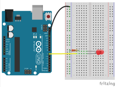
Now, let’s build a circuit using the blink example again.
First, go around the Engineering Design Studio and find
- a breadboard
- some jumper wires
- a Light Emitting Diode (LED)
- one ±220 ohm resistor

Remember to always disconnect your Arduino from your laptop or an external power source when you work on your circuit.
Connect the anode (longer leg) of the LED to pin 7. Connect the cathode (short leg) to ground through a resistor (between 220ohm – 1kilohm is fine). Plug the Arduino into your computer and get ready to upload the code!
Remember, you need to select which board you’re using in the “Tools” menu, and the port the board is connected to. This insures the IDE prepares the code for the right kind of board, and tries to communicate on the proper port.
Now your LED on the breadboard blinks!
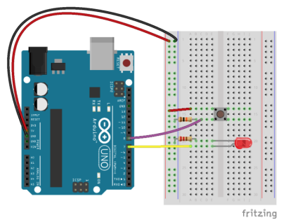
Now let’s get some input. We’ll start with the hardware.
Go around the Engineering Design Studio and find
- a 10 kohm resistor
- a simple push button
You’re probably asking what the devil that 10kilohm resistor is doing in there.
When you press the button as wired above, the voltage flows to the Arduino pin, bypassing the 10k resistor (because electricity follows the path of least resistance, and the 10k is pretty big). When the button is not pressed, it provides the pin a reference to ground. Without that reference, the pin would be “floating” and may pick up all sorts of stray electricity. This 10k resistor is your insurance that you will always get the proper reading from the switch.
Done with the hardware? Now the code:
void setup() {
  // put your setup code here, to run once:
  pinMode(7, OUTPUT);
  pinMode(8, INPUT);
}
Here, we’re adding pin 8 as an INPUT. The Arduino can now read the voltage on the pin and let us know if it is HIGH or LOW.
Now on to the loop() where there’s some more new things:
void loop() {
  // put your main code here, to run repeatedly:
  if (digitalRead(8) == HIGH) {
    digitalWrite(7, HIGH);
    delay(1000);
    digitalWrite(7, LOW);
    delay(1000);
  } else {
    digitalWrite(7, LOW);
  }
}
This introduces a number of new ideas. Let’s start with digitalRead(). It is a function that will check the voltage of the pin you give as an argument. digitalRead() returns a value, either HIGH or LOW, depending on the state of the pin. If there is 5V on the pin, it will give us HIGH, 0V will give us LOW.
We want the LED to blink when the button is pressed, that is, the voltage on the pin is HIGH. We can test this condition with an if() statement. if() check to see if something is true or false. If the condition is met (true) it will execute the code in the curly brackets that follow it. If not, it will ignore that code.
Note that we’re using == in the if() statement. This is very different than a single =. This is one of those lovely aspects of programming that is going to cause you more headaches moving forward. Sorry about that. The == is a comparison. A single = sets a value.
We can read the code above like this : “Read the value of pin 8, if it is HIGH, blink the LED… “. The else is an aspect of the if() statement that helps control the flow of your program a bit better. It’s not necessary in this instance, but it’s not the worst thing to include either. All it’s doing here is adding an addendum to the above : “Read the value of pin 8, if it is HIGH, blink the LED. Else, if the value is LOW, don’t turn the LED on at all”.
Recommended Links
Recommended books
- Banzi, Massimo, Getting Started with Arduino
- Igoe, Tom, Making Things Talk
- Margolis, Michael, Arduino Cookbook
- Roberts, Dustyn, Making Things Move
Homework
- Read the article by Donald Norman about why Attractive things work better
- Read There are no Electrons (available via NYU Classes resources section ⇒ other resources)
- Go through the Arduino Projecthub and find projects that are somehow similar to your first ideas for your machine.

